
Angular Deviation (θz) in Permanent Magnet is defined as the angle between a magnet's internal magnetization direction and its geometric reference axis (e.g., designated surface or centerline).
Sintered NdFeB magnets typically exhibit θz?between 0° and 7°, with ≤5° being a common production tolerance.
Why This Matters
Even a small angular deviation can cause significant magnetic field distortion: ?
- ? ????Reduced normal field component (Bz)
- ? ????Increased in-plane components (Bx, By) ? ??
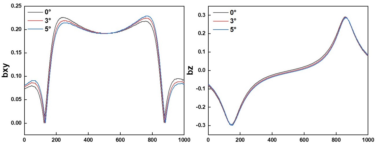
If field deviation exceeds just a few percent, precision applications, such as sensors, medical devices, and actuators, are at risk of critical performance degradation.
This article explores how angular deviation develops during manufacturing, what our data shows about spatial trends, and what manufacturers can do to control it.
What the Data Shows: Spatial Variations Are Real
We conducted an analysis of angular deviation in a sintered NdFeB magnet block. The block dimensions were 34 × 50.7 × 43.7 mm, ? ?with ? ?the following sampling details:
-?50.7 mm?corresponds to the?non-pressed, non-oriented direction. After grinding off 0.6 mm, three slices were taken from the?front, center, and rear, each 1.73 mm thick, corresponding to spatial ? ?coordinates?X1, X2, X3.
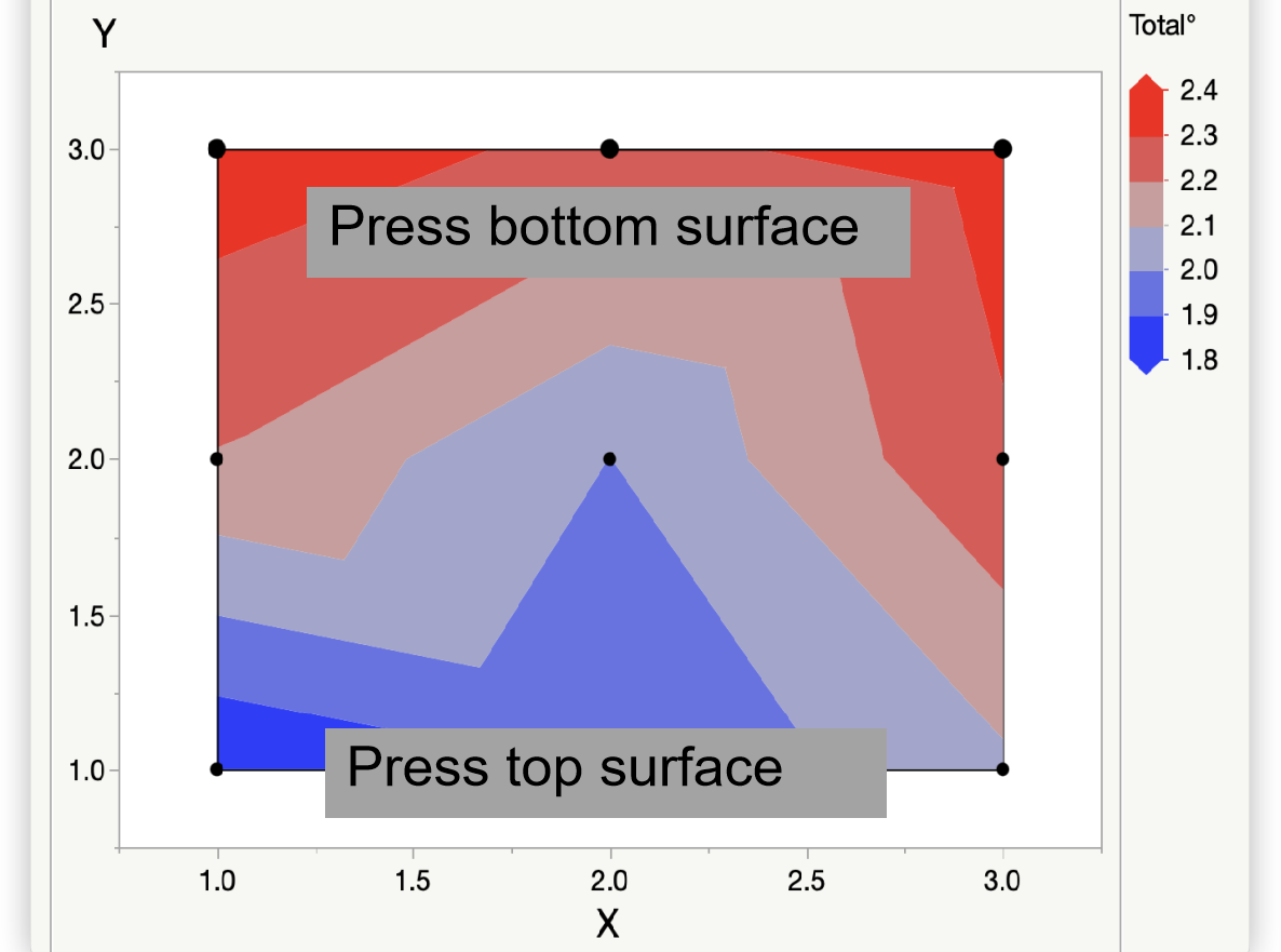
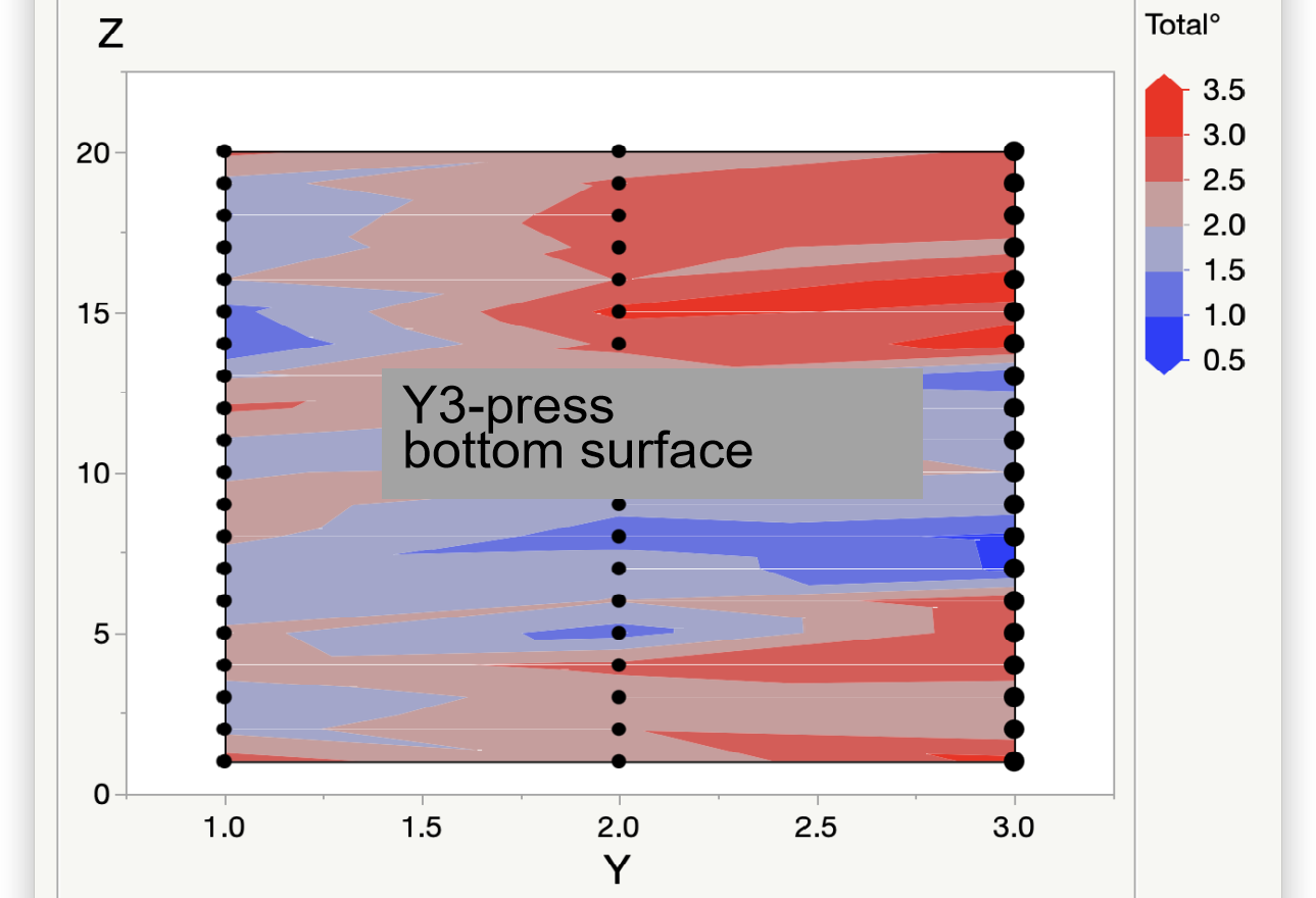
-?43.7 mm?is the?pressing direction. After grinding off 0.6 mm, three slices were taken from the?top, center, and bottom, each 6.845 mm thick, corresponding to?Y1, Y2, Y3, with?Y3 being the pressed bottom surface.
-?34 mm?is the?orientation direction. After removing 0.6 mm from the surface, 20 layers were sliced at 1.3 mm intervals, corresponding to spatial coordinates?Z1 through Z20.?In total,?180 sampling positions?were measured for angular deviation, and the resulting data was used to analyze the?spatial distribution of angular deviation?within the block.
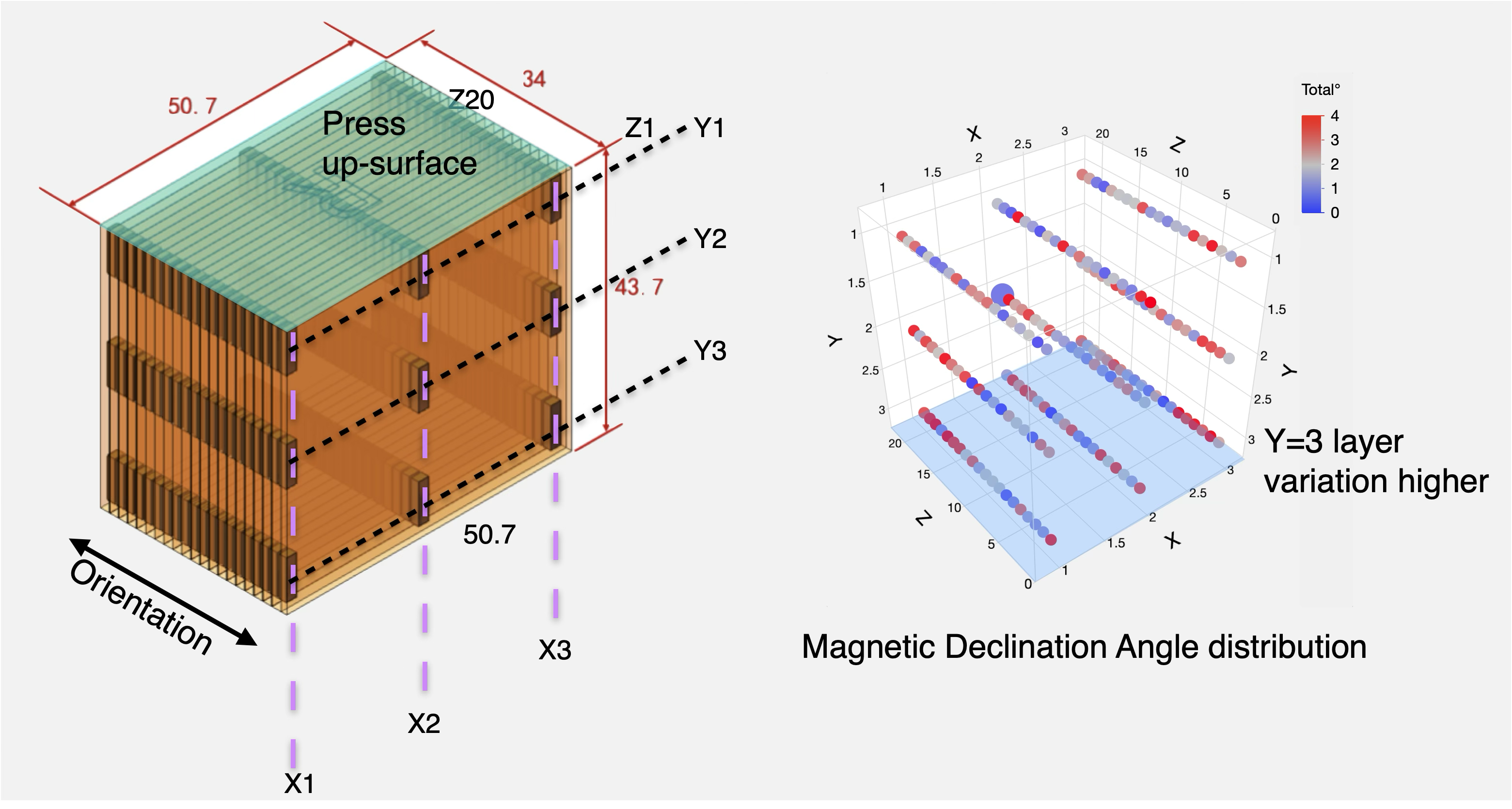
The results revealed clear?spatial patterns?in angular deviation.
|
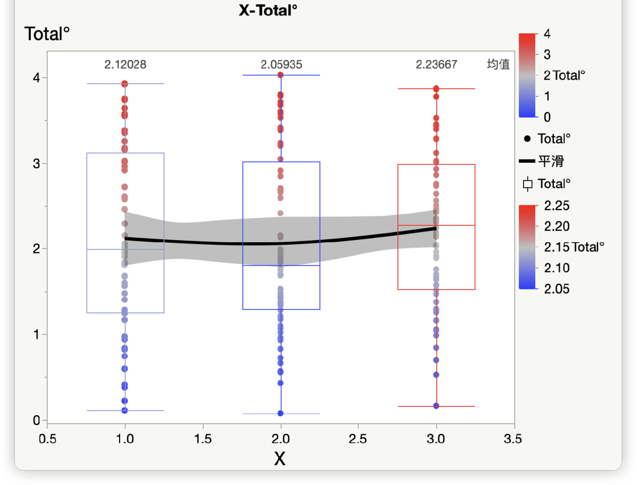
Along the Non-pressed, Non-Oriented (X) - No obvious trend |
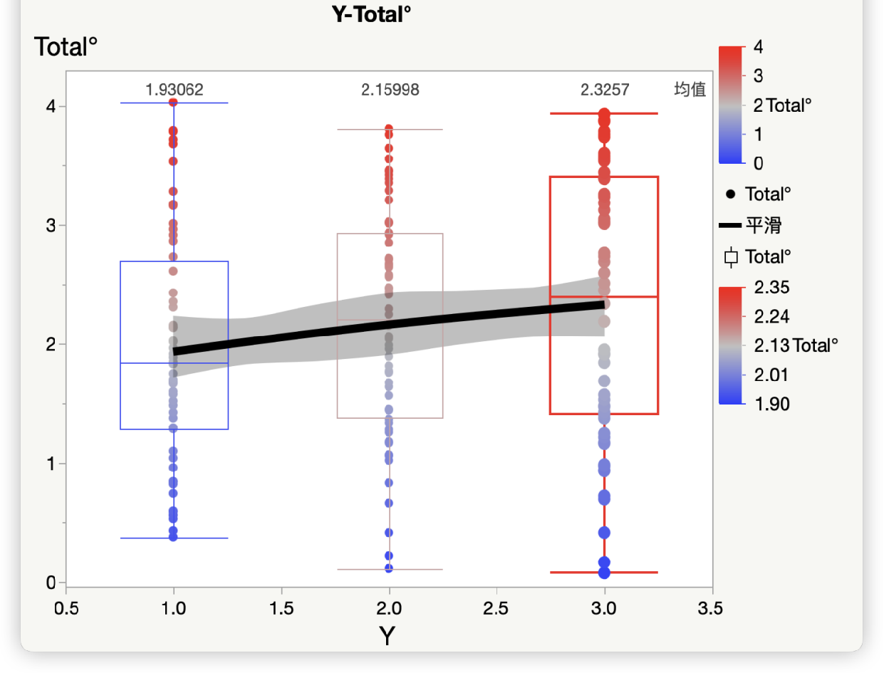
Along the Pressing (Y) Direction: ? - The bottom surface (Y3) has θz?35% |
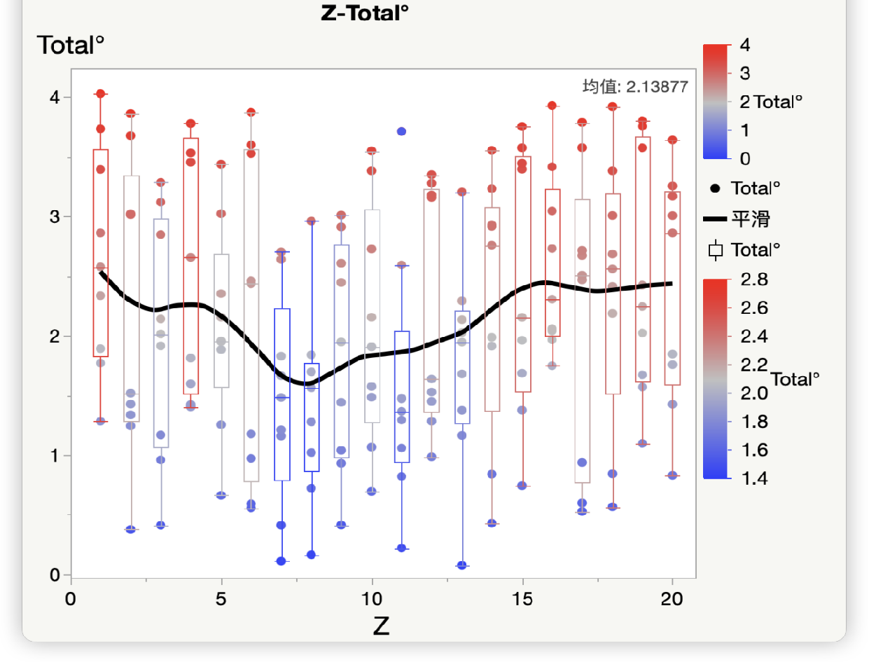
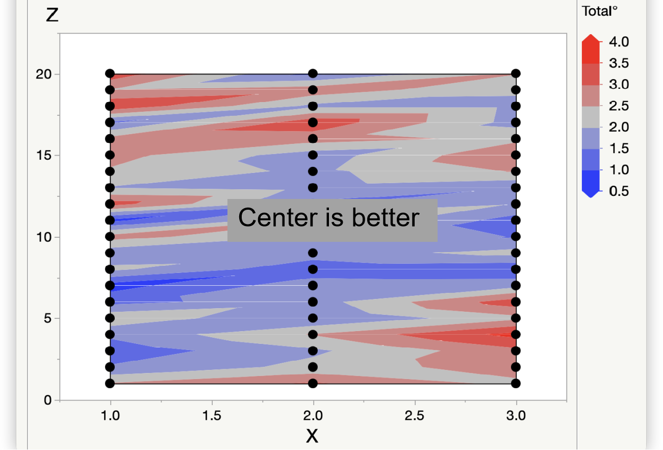
Across the oriented (Z) axis: - Center layers (Z10) show θz?less than 2° - Edge layers (Z1 and Z20) reach over 4°? |
|
|
|
| 2D ? ? ? ? ?Contour ? ? ? ? ?Mapping across all planes confirm a gradual shift in θz??across all planes – highlighting the ? ? ? ? ?cumulative impact of process variation.?? | ||
|
|
|
What’s Causing the Deviation
Several steps in the manufacturing process can introduce angular deviation. Here are the key contributors:
| Stage | What Happens |
Effect on θz |
| Orientation Pressing | Non-uniform particle alignment | Baseline deviation of 0.5°- 2° |
| Isostatic Pressing | Density shifts and deformation | Adds ~0.5° |
| Sintering | Anisotropic shrinkage (20%?axial vs.?5%?radial) | Sustains 0.5°- 2°baseline |
| Machining | Fixture misalignment | Adds another 0.5 - 2°? |
How We Can Reduce θz: Actionable Solutions
Based on our findings, here are three strategies that show promise:
1. Mold Calibration with Isotropic Materials
·?Calibration using isotropic materials can verify that the magnetic field aligns perpendicular to the intended magnetization ? ?direction. ?
2. Design Adjustments ?
·?Shorten the pressing (Y) axis to reduce powder settling
·?Widen the non-oriented (X) axis size to reduce deformation risk ?
3. Streamline the Process
·?Eliminating isostatic pressing can help reduce handling deformation? ?
The Goal: θz?≤?3°
By implementing these strategies, we estimate a?40% improvement?in angular deviation, reducing θz?to?3° or less — a level that significantly enhances magnetic field quality in precision applications.
We’ll be publishing our data after implementing these strategies in?Q3 2025—stay tuned!
### APPENDIX: ? ?Angular Deviation Testing Methodologies
Technical Principles for Engineering Teams?
| Method | Core Principle | Key Specifications |
|
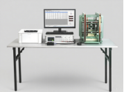
Helmholtz Coil
|
Measure the magnetic dipole moment components in three mutually orthogonal directions to compute?the?magnetic moment orientation |
GR&R: 3% · Cycle time: 5s · Max sample dimension: Determined by the coil diameter |
|
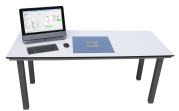
MagCheck
|
6-DOF inverse field modeling to compute?magnetic moment vector |
GR&R: 6% · Cycle time: 6s · Rectangular magnets: Maximum dimension ≤ 80 mm Cylindrical/Ring magnets: Diameter ≤ 100 mm, Height ≤ 50 mm |
|
MagCam
|
Hall sensor array + Bz inversion to map?surface magnetization vectors | Resolution: 3% · Cycle time: 20s ·Max sample dimension: 12.7 x 12.7 mm |
Why Helmholtz Coil Was Chosen: ?
- Scalability: Cost-effective for mass production environments
- Reproducibility: Achieves 3% accuracy across different lab setups??
- Practicality: Supports production-sized samples
Access NdFeB Permanent Magnet Material Property Datasheets?
Try Our Magnetic Calculator
Use this tool to estimate performance, calculate load lines, and visualize demagnetization curves.